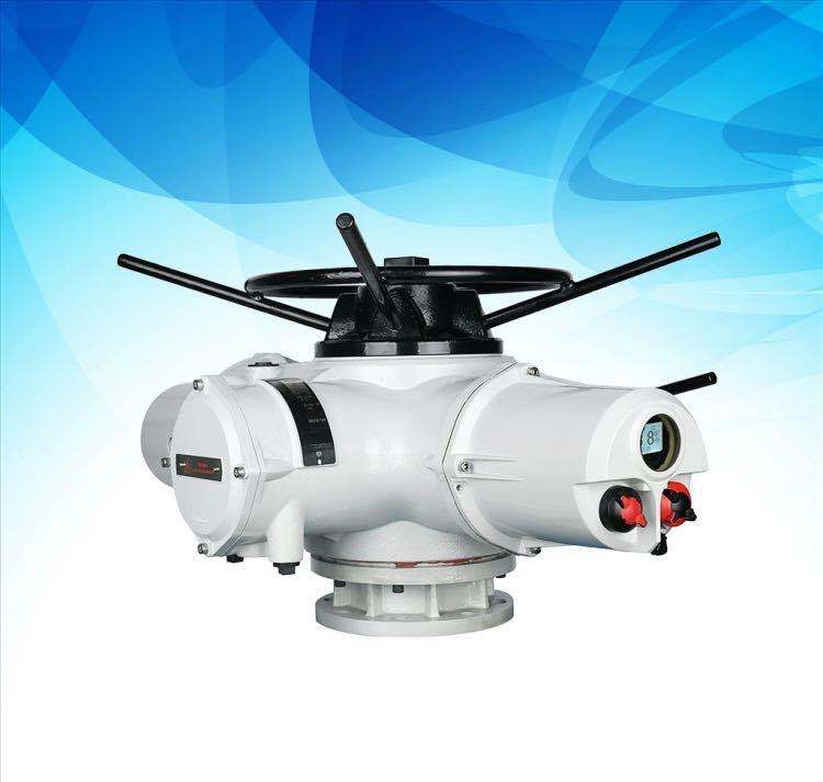
The working principle and installation method of pneumatic control valve
Release time:
2024-10-30 15:16
Pneumatic control valveThe working principle and installation method
Pneumatic control valve is one of the industrial process control instruments widely used in petroleum, chemical, electric power, metallurgy and other industrial enterprises. In chemical production, the control valve is indispensable in the control system. It is an important part of industrial automation system.

The pneumatic regulating valve uses compressed external gas as the power source, the cylinder as the actuator, and the electric inlet and outlet positioner, converter, solenoid valve, holding valve and other accessories to drive the inlet and outlet to realize the switch or proportional adjustment, and pick up the control signal from the industrial automation control system to complete the adjustment of various process parameters such as the flow, pressure and temperature of the pipeline medium. The air propulsion control valve has the characteristics of simple control, fast response and intrinsic safety, so no additional explosion-proof measures are required. Air propulsion control valve is usually composed of air propulsion actuator and control valve connection, installation and commissioning. Air propulsion actuators can be divided into single-acting and double-acting. Single-acting actuators have a return spring, while double-acting actuators do not have a return spring. In the event of loss of origin or sudden failure, the single-acting actuator can automatically return to the activated or sealed-off state of the inlet and outlet settings. Air propulsion control valves are divided into air-open and air-closed types according to the action form, the so-called normally open type and normally closed type. The air propulsion opening or air propulsion sealing of the air propulsion control valve is usually realized by the positive and negative effects of the actuator and the different assembly methods of the valve state structure.
Pneumatic control valveThe external gas open type (normally closed type) means that when the external gas pressure on the diaphragm head increases, the inlet and outlet move in the direction of increasing the opening degree. When the upper limit of the input external gas pressure is reached, the inlet and outlet are fully open. On the contrary, when the external gas pressure decreases, the inlet/outlet operates in the sealing-off direction. When there is no external gas input, the inlet and outlet are completely sealed. Usually, we will open the external gas regulating valve called fault seal off valve.
The direction of action of the gas-closed type (normally open type) is just the opposite of the gas-open type. When the external gas pressure increases, the inlet and outlet move along the sealing direction; when the external gas pressure decreases or does not exist, the inlet and outlet should be turned to the starting direction or completely started. Usually, we will seal off the external gas regulating valve called fault start valve.
The choice of gas on/off is based on the safety of the process. When the gas supply is cut off, whether the regulating valve is safe in the sealing position or in the starting position. It is safer to choose external gas to start the import and export, because once the gas supply is stopped, it is more appropriate to seal the import and export than to start completely. If the air supply is interrupted and the fuel valve is fully activated, overheating may occur. Another example is a heat exchange device cooled by cooling water, in which a thermal material exchanges heat with cooling water in a heat exchanger and is cooled. The external gas compressor regulating valve is installed on the cooling water pipe, and the cooling water volume is controlled by the material temperature after heat exchange. When the gas supply is interrupted, the regulating valve should be in the starting position, which is safer. External gas seal-off (I. e. FO) control valve shall be selected.
2022-12-19


